What Is EMI? Types, Sources, Effects, and EMI Shielding
Understand EMI, conducted vs radiated noise, device impacts, and shielding tips.
What EMI is and what it means for engineering
What EMI stands for is electromagnetic interference. In plain terms, it is unwanted electrical noise that disturbs electronic equipment. It can shift signals, cause resets, or corrupt data. That is why engineers take it seriously during design and tests.
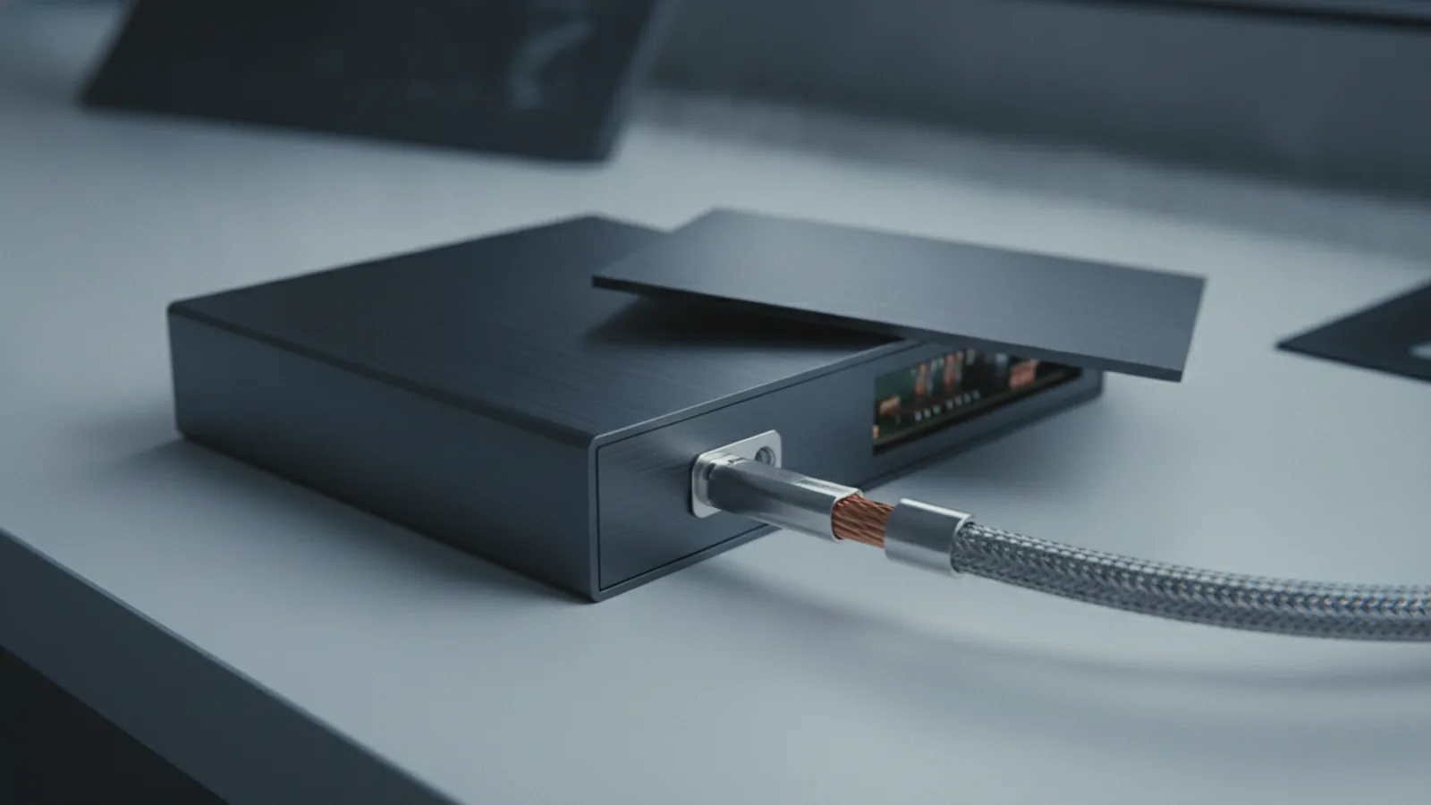
What is an EMI shield, you ask. An EMI shield is a barrier that blocks or reduces that unwanted coupling. It can be a metal can, a conductive coating, or a grounded enclosure. The goal is to control the path noise takes into a device.
What is EMI meaning in daily work is simple. EMI is the interference problem. What is an emi file is not part of this topic, and it is likely from a different domain. For electrical engineering, focus on the electrical noise meaning of EMI, not file formats or finance terms.
EMI also connects to electromagnetic compatibility (EMC). EMC is the outcome. It means a product works as intended without creating harmful noise. So when someone says what do you mean by EMI, they usually point to both EMI effects and EMC goals.
- EMI is the unwanted noise source.
- EMC is the requirement that limits harm.
- EMI shielding is one mitigation strategy inside EMC work.
EMI types: conducted vs. radiated interference
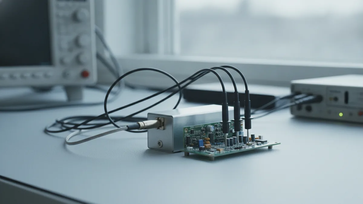
emi types describe how the noise travels. The two main categories are conducted vs. radiated EMI. Conducted noise moves along cables and conductors. Radiated noise moves through space using electric or magnetic fields.
Conducted EMI usually appears on power lines and signal lines. It couples through the wiring harness, then spreads across the circuit. If a device switches current fast, it can inject ripple that rides on supply rails.
Typical examples include switching converters and motor drivers. A sharp current edge can create voltage steps. Those steps can show up on nearby analog inputs as ripple or offset.
Radiated EMI couples through fields that radiate from traces and cables. Long wires can behave like antennas. Board edges and enclosure seams also affect radiation paths.
Radiated noise can be hard to repeat. It may change when you move a cable bundle. It can also vary with enclosure placement and grounding quality.
- Conducted EMI: noise on power rails, noise on data lines, common-mode coupling.
- Radiated EMI: interference picked up by nearby receivers, emissions from fast edges.
Sources of EMI: artificial and natural interference
sources of emi can be inside a product or outside it. In most designs, the largest driver is fast switching. That includes PWM edges, clock transitions, and rapid load steps.
Quick changes in voltage and current generate a wide range of frequencies. Some of that energy couples into other parts of the circuit. Once it finds a victim path, it becomes a system-level issue.
Common artificial EMI sources
Artificial sources are built into devices and test setups. Power conversion stages are a top cause. Digital clocks and bus activity also inject high-frequency energy into traces.
High current switches can produce ringing. That ringing may couple into adjacent nets through capacitance or inductance. It may also couple onto cables that exit the enclosure.
- Switch-mode power supplies and DC-to-DC converters
- Motor drivers, inverters, and gate drive circuits
- High-speed clocks and data buses
- Relays and solenoids from contact bounce and arcing
- Static events during setup and handling
Natural EMI sources and RFI conditions
Natural EMI can also show up in the real world. Lightning can inject high energy into conductors. That can upset nearby electronic systems.
Another source is radio frequency interference (RFI). Local transmitters, antennas, and wireless equipment can overlap your operating band. When that happens, you may see random faults that track with the radio environment.
Space weather is less common for typical consumer tools. Still, it can matter for specialized links. Long outdoor links are where this risk is more relevant.
Effects of EMI on devices: what breaks in practice
effects of emi depend on the victim circuit. The same noise can be harmless in one block and fatal in another. It all comes down to sensitivity, coupling strength, and signal margin.
On communication links, EMI can raise the error rate. You may see corrupted packets, retries, or dropped connections. Over time, that can look like a software reliability issue, even when the root cause is electrical noise.
On sensors, EMI adds junk to the signal path. That junk can shift readings and disturb control loops. If the system uses feedback control, small signal errors can grow into bigger behavior problems.
On digital logic, EMI can break timing and state. It may cause unintended transitions. It can also lead to resets when the supply rails or reference signals dip or shift.
- Bit flips, checksum errors, and bad frames
- Dropouts, retries, and unstable links
- Jitter in analog reads and control errors
- Resets and watchdog triggers
If you are troubleshooting, look for coupling patterns. Repeat the issue when you move or reroute cables. Compare behavior with and without specific loads switched.
Also note common search confusion. Terms like what is emi in finance refer to a different meaning. For electronics work, ignore that and treat EMI as electromagnetic interference.
EMI shielding and mitigation techniques that work
emi shielding helps reduce unwanted coupling. It does this by blocking fields, redirecting current, and improving grounding paths. A shield works best when it is correctly connected to ground.
Mitigation should follow a system plan. Start at the noise source. Then control the coupling path. Finally, protect the victim circuit with filtering and layout changes.
Good teams test after each change. That shortens the loop between design and fixes. It also helps you avoid false assumptions.
Shielding methods: materials and grounding
Common shielding materials include copper, aluminum, steel, and conductive coatings. Metals block fields by providing a low-impedance return path. Conductivity and thickness matter for effectiveness.
Grounding is not optional. A poorly grounded shield can behave like an antenna. Use a solid connection strategy for seams, cable entries, and panel joints.
Seams are a frequent failure point. If a case has gaps, noise can leak through. Use conductive gaskets or overlap designs to reduce those gaps.
- Use metal enclosures with proper bonding at seams
- Keep shield connections short and low impedance
- Control gaps in lids, vents, and mounting points
- Use shielded cables with correct termination
Layout, filtering, and cable practices
Shielding alone is rarely enough. Layout decisions often determine coupling strength. Keep loop areas small, especially for switching currents.
Route sensitive signals away from noisy edges. Place filtering close to the device pins that need it. A filter far away loses impact due to added trace inductance.
For conducted noise, common-mode chokes and ferrite beads can help. For radiated noise, controlled cable routing matters. Twist pairs and route along reference planes when possible.
- Shorten current return paths and shrink high-current loops
- Place decoupling capacitors near the load and driver
- Add input filtering at the victim side when needed
- Use ferrites and common-mode components on cables
- Re-check with a plan for both conducted and radiated checks
These are mitigation strategies for EMI, not magic fixes. They reduce coupling and improve EMC performance over time.
Where EMI shielding matters most
EMI shielding is critical in many fields where reliability is non-negotiable. Telecommunications need stable links and low error rates. Even small noise can raise packet errors and reduce throughput.
Aerospace and industrial systems also demand strong EMC margins. Equipment often runs in harsh environments with long harnesses. That makes both conducted and radiated paths more likely.
Medical devices require careful control of interference. The system must avoid upsetting readings and must also avoid injecting harmful emissions. That is why EMC testing and shielding design are part of early engineering.
In short, if your system processes precise signals or controls safety-critical actions, EMI matters. Shielding is one tool among many. It works best when paired with solid layout and clean power design.
Conclusion: what you should take away about EMI
what emi means in engineering terms is unwanted electromagnetic noise. It causes malfunction through coupling into power, signals, or logic timing. That is why you study emi types, track sources of emi, and verify effects of emi.
Mitigation uses more than one lever. Use shielding to block or redirect fields. Use layout and filtering to cut coupling paths. Then test each change so you can trust your results.
One last point: searches like what is an emi insurance or what happened to emi are not about electromagnetic interference. This guide is for the electronics meaning of EMI, and for how EMI shielding supports EMC goals.
FAQ
- What is EMI and what does EMI stand for?
- EMI stands for electromagnetic interference. It is unwanted electrical noise that disturbs electronic devices.
- What is an EMI shield and how does it help?
- An EMI shield is a conductive barrier that reduces unwanted coupling. It works best when properly grounded and sealed at seams.
- What are EMI types?
- The two main EMI types are conducted EMI and radiated EMI. Conducted EMI rides on cables, while radiated EMI couples through fields.
- What are common sources of EMI?
- Common sources include switching power supplies, motor drivers, clocks, and fast digital edges. Natural RFI from nearby transmitters can also interfere.
- What effects can EMI have on electronic devices?
- EMI can increase data errors, cause communication dropouts, and trigger resets. It can also add jitter to sensor readings.
- What is the link between EMI and EMC?
- EMI is the interference problem. EMC is the requirement that products operate safely without causing harmful noise.